What Are Mold Parts and How Do They Work?
Mold Parts are the working components inside a mold that shape, guide, cool, and release a product. In injection molding, molten material enters through a sprue and runner, then passes through a gate into the cavity. The core and cavity form the part’s outer and inner surfaces. Their fit affects dimensions, surface finish, and whether the finished piece can be removed cleanly.
Other components keep the process controlled. Guide pins align the mold halves, while ejector pins push the solidified part away after cooling. Cooling channels carry water or another temperature-control fluid through the mold. Vents let trapped air escape near the cavity edges. Small details matter. A blocked vent or worn ejector pin can leave visible marks, cause sticking, or interrupt production. The exact layout depends on the part’s shape, material, and production needs.
Understanding how these parts work together helps engineers diagnose defects and make informed design choices. For example, uneven cooling can cause warping, while poor alignment may create a mismatch along the parting line. These symptoms can have more than one cause, so inspection and process data are important. Not every mold uses the same components or arrangement. That variation is easy to overlook. A reliable explanation should connect each component to its function, while recognizing that real molds require careful design, maintenance, and testing.
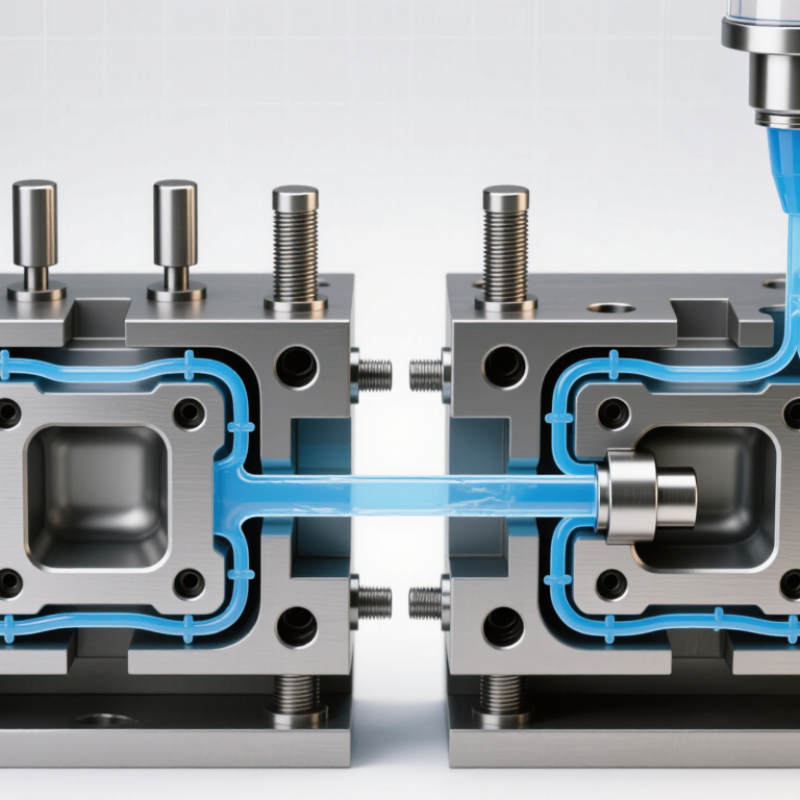
What Mold Parts Are and What They Form
A mold is a shaped tool that gives material its form.
In injection molding, two main sections close around a cavity, the empty space that defines the part’s outside. The core forms inner surfaces, such as a hollow opening or recessed feature. The cavity and core must align closely. Even a small mismatch can leave a visible step.
Other mold parts guide material and control release. A sprue carries molten plastic into runners, which direct it toward the gates and cavity. Cooling channels help the material set, while ejector pins push the finished part free. Simple parts may need only a few pins; deep or delicate shapes often need more careful placement. The gate also leaves a small mark, so its location can affect appearance.
The parting line is where the mold sections meet. It may appear as a fine seam on the product. I would not call every seam a flaw, but it should be checked against the part’s purpose and finish requirements. Mold design also varies with material, geometry, and production method. A drawing can look tidy, yet actual parts may reveal sticking, uneven cooling, or marks that need adjustment.
How the Mold Base and Cavities Fit Together
A mold base is the steel framework that holds a mold’s working components in position. It usually includes mounting plates, support plates, guide pins, and bushings. The cavity sits in one half, while the core sits in the other. Together, their shaped surfaces form the space where molten plastic becomes a part.
When the mold closes, guide pins enter matching bushings and help the two halves align. The cavity shapes the part’s outside; the core forms its inside. Their meeting edge creates the parting line, which may leave a faint seam. Alignment matters. Even slight wear or debris between mating surfaces can cause flash, uneven edges, or damage over repeated cycles.
The mold base also carries loads from the press and supports cooling channels and other components. During setup, technicians check plate contact, pin movement, and cavity-to-core fit before production. A smooth fit is not automatically a good one; trapped air or poor cooling can still affect the part. A polished layout can hide practical problems. That is worth remembering when drawings look perfect.
What Each Core Mold Component Does
A mold is more than two metal halves. Its core usually forms internal features, such as a bottle’s hollow interior, while its cavity shapes the outer surface. The mold base holds these parts and provides support under clamping pressure. Where the halves meet is the parting line, which can leave a faint seam on the finished piece. Small details matter. A neat diagram can make the layout seem simple, but real designs often involve trade-offs between part shape and easy release.
The runner carries molten material through the mold, and the gate directs it into the cavity. Cooling channels remove heat through the steel; uneven cooling can cause warping or longer cycle times. After the material solidifies, ejector pins push the part free. Guide pins help align the mold halves during closing, while small vents give trapped air a way out. If vents are blocked or too shallow, burn marks or incomplete filling may result. Each component affects the others, so changing a gate or cooling path can have unexpected effects.
Tips: Inspect the parting line, gate area, and ejector marks on sample parts. These visible clues can point to alignment, filling, or release issues. Don’t assume one adjustment will solve every defect.
How Mold Parts Guide the Forming Cycle
A mold guides each forming cycle through coordinated movement, heat, pressure, and timing. The clamp closes the mold and holds its halves together. Melt then travels through the sprue, runners, and gate into the cavity. These channels shape flow; a poorly balanced runner can leave one cavity filling sooner than another. Small details matter.
Cooling begins while pressure is maintained, helping the part hold its shape as the material solidifies. Ejector pins then push the part free, and the mold closes again. PlasticsEurope’s Plastics—The Fast Facts 2024 reports 413.8 million tonnes of plastics produced worldwide in 2023. That figure covers plastics production broadly, not injection molding alone, but it shows why repeatable cycles matter at scale. Sensors can track cavity pressure and mold temperature, yet readings still need skilled interpretation. A cold corner may cause visible sink marks or uneven shrinkage. Still, an ideal test cycle is not a guarantee of steady production; material changes and tool wear can shift results. That part is easy to underestimate.
What Are Mold Parts and How Do They Work?
How mold parts guide a representative injection-molding cycle
The sprue, runners, and gate carry molten plastic into the cavity. The cavity and core shape the part; cooling channels remove heat; then ejector pins release the cooled part as the mold opens. The percentages are illustrative typical cycle shares, not fixed values—actual timing varies with the material, part geometry, and mold design.
How Mold Designs Differ Across Applications
Mold designs change with the part being made, the material, and the required production volume. A simple cap may use a two-part mold with a straight opening direction. A housing with side holes may need sliding cores that move before ejection. These moving sections add cost and maintenance needs. Small details matter.
Material also shapes the design. Hot-running plastics may need carefully placed cooling channels to control temperature and reduce warping. Thick sections cool slowly, while thin walls can freeze before the mold fills. For metal casting, the mold must handle heat and allow gases to escape. The ejector pins, gates, and vents must suit each part; copying a layout from another job can cause defects. A design can look neat on screen and still trap a part. That is easy to underestimate.
Tips: Check the part’s draft, wall thickness, and likely shrinkage before finalizing the mold. Ask how often the mold will run and how it will be cleaned. A quick review with production staff can reveal practical issues. Some choices still need testing.