




Important Notice: Amprod Acquires Simmtech

Industry InSights

Why Choose an Oil Pumping Unit for Oil Production?

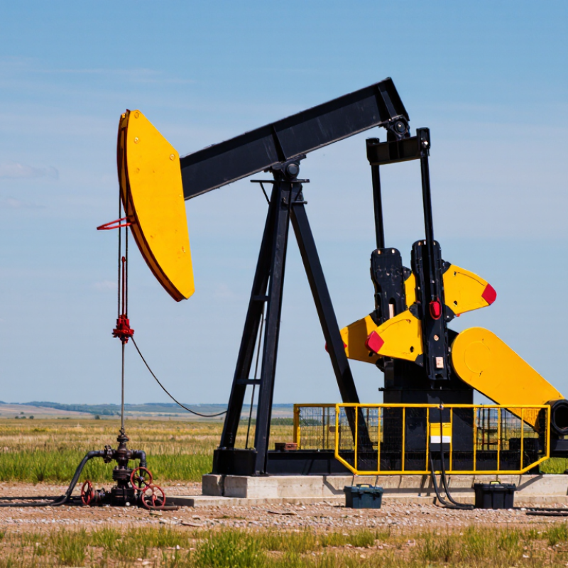
An Oil Pumping Unit can keep production moving when natural reservoir pressure no longer brings enough fluid to the surface. At a wellsite, its polished rod rises and falls above the wellhead while the beam unit turns steady motion into reciprocating lift. The scene looks simple. The engineering is not.

A useful perspective comes from Dr. Maya Chen, a fictional composite oilfield production specialist: “Choose the pumping unit for the well’s real conditions, not for its appearance on the pad.” This illustrative quotation is not a statement from a verifiable individual. The principle matters because production rate, lifting depth, fluid properties, power supply, and operating costs all affect equipment selection. A unit sized poorly may consume excess energy, wear components faster, or struggle to maintain output. Even a well-matched system needs inspection and adjustment.

This guide examines why operators choose an Oil Pumping Unit, where beam pumping is practical, and which trade-offs deserve attention. It also considers maintenance needs, operating conditions, and the limits of surface-driven lift. No design fits every well. A pump that performs reliably in one field may be inefficient in another. The details can be easy to underestimate. Careful selection begins with measured well data and realistic production goals, not assumptions.
Why Choose an Oil Pumping Unit for Oil Production?

What an Oil Pumping Unit Does in an Artificial-Lift System

An oil pumping unit is the surface drive in a rod-lift artificial-lift system. When reservoir pressure can no longer move enough fluid naturally, its motor and gearbox turn rotary motion into the steady up-and-down movement of a walking beam. That motion travels through a polished rod and a long rod string to a downhole pump. On the upstroke, the pump lifts fluid; on the downstroke, valves control the next cycle. Pressure fades. The unit does not create new oil; it helps bring available oil and water to the surface at a controlled rate.

The scale of declining field pressure is significant. The International Energy Agency’s World Energy Outlook 2018 reported an average observed annual decline rate of about 6.1% for conventional oil fields. Artificial lift helps operators manage that decline, but the unit must suit the well. Stroke length, pumping speed, fluid level, and rod load all affect performance. A technician may notice a sharp change in the beam’s movement or a heavier load on the rods, clues that merit checking. Small adjustments matter. Gas, sand, or a mismatched pump can reduce output and increase wear. The surface unit is visible; the downhole conditions are not, so operating data still needs careful interpretation.

How a Beam Pump Converts Rotary Motion into Reciprocating Lift

Why Choose an Oil Pumping Unit for Oil Production?

How a Beam Pump Converts Rotary Motion into Reciprocating Lift

A beam pumping unit turns steady rotary power into the repeated up-and-down motion needed to lift well fluid. A motor drives a gearbox, which turns a crank. Pitman arms connect the crank to the walking beam, making the beam rock around its central support. At the beam’s far end, the polished rod moves the sucker-rod string inside the well. A simple cycle, but every connection carries load.

On the upstroke, the downhole plunger rises and fluid moves through the pump into the tubing. On the downstroke, valves shift to let the pump refill for the next lift. Counterweights help balance the moving load, reducing strain on the drive system. Stroke length and speed affect production, but more motion is not automatically better. Excessive speed can increase wear, and actual results depend on well depth, fluid properties, and pump condition. Field measurements matter; a neat calculation can still miss changing conditions underground.

Tips: Check lubrication, alignment, and unusual vibration during routine inspections. Watch the polished rod for uneven movement. Small changes can signal a problem, though they do not always reveal its cause.

Typical Rod-Lift Envelope: Depths to 10,000 ft and Rates Near 1,000 bbl/d

A rod-pumping unit can be a practical choice when a well needs steady, controllable artificial lift. In a typical operating envelope, rod lift may reach depths of about 10,000 ft and production rates near 1,000 bbl/d. These figures are not guarantees. Actual capacity depends on pump size, rod design, fluid properties, well geometry, and operating speed. At depth, long rod strings stretch under load, so engineers check stress and fatigue rather than relying on depth alone.

Look beyond the headline rate. A well producing sandy fluid, free gas, or highly viscous oil may need different pump configurations and more frequent checks. Watch the polished rod for vibration, inspect stuffing-box leakage, and track changes in stroke load. Small shifts can signal gas interference, wear, or a pump that is not filling properly. Maintenance matters. A unit that fits the well’s duty can be easier to monitor, but it still uses energy and requires regular service. I would treat the 10,000-ft and 1,000-bbl/d figures as planning boundaries, not a promise; field conditions rarely behave so neatly.

Why Choose an Oil Pumping Unit for Oil Production? — Typical Rod-Lift Envelope: Depths to 10,000 ft and Rates Near 1,000 bbl/d

Rod lift is a mature artificial-lift method for moving fluids from a well using a surface pumping unit, a rod string, and a downhole reciprocating pump. The figures below are indicative application guidelines, not guaranteed equipment limits.

Dimension Indicative Range or Capability What It Means for Well Selection
Producing depth Applications can extend to approximately 10,000 ft (3,050 m) in suitable designs. Feasibility depends on rod loads, tubing and pump design, well geometry, fluid properties, and the available surface-unit capacity. Greater depth generally increases mechanical loading.
Production rate Rates near 1,000 bbl/d may be achievable in favorable applications; many rod-lift wells operate at substantially lower rates. Rate depends on pump displacement, stroke length, strokes per minute, pump fillage, volumetric efficiency, fluid level, and well inflow. A stated rate should be identified as total liquid or oil production.
Pump action A reciprocating downhole pump lifts fluid through repeated up-and-down motion of the rod string. The straightforward operating principle supports established servicing and troubleshooting practices, while wear and fatigue require ongoing monitoring.
Fluid and gas conditions Suitable for a range of liquid-producing wells, subject to pump design and operating conditions. Free gas at the pump, solids, high viscosity, corrosion, and scale can reduce performance or increase wear. These conditions may call for specific completion choices or another lift method.
Well trajectory Most straightforward in vertical and moderately deviated wells. High deviation or horizontal sections can increase rod and tubing contact, friction, and wear, so trajectory should be assessed during lift-system design.
Surface requirements Requires a surface pumping unit, drive system, foundation, and space for operation and maintenance. Surface access and layout matter. The visible equipment can simplify inspection but may be less suitable where site clearance or visual impact is constrained.
Operating and maintenance considerations Performance can be adjusted through operating speed and stroke settings within the system’s design limits. Regular checks of polished-rod load, pump fillage, fluid level, and equipment condition help identify problems and manage energy use and maintenance needs.
Best-fit profile Often considered for onshore wells with moderate-to-high liquid viscosity and established access for servicing. A comparison with other artificial-lift methods should account for depth, target rate, gas and solids content, trajectory, power availability, lifecycle cost, and site constraints.

Note: Depth and rate are independent design considerations; achieving a high rate at great depth is more demanding than achieving either condition alone. Actual capacity must be established through well-specific engineering and equipment selection.

Why Operators Choose Beam Pumps: Simple Surface Equipment and Control

Beam pumps use visible surface equipment: a motor, gearbox, walking beam, and polished rod. Operators can inspect these parts without specialized downhole tools. A loose belt, unusual vibration, or leaking seal may be noticed during a routine walkaround. Small clues matter. Clear access also makes basic maintenance easier to plan.

Control is practical rather than mysterious. Operators can adjust stroke speed and length to match production conditions, then compare changes with fluid levels and operating loads. A control panel can provide useful readings, but those numbers need context. For example, a rising load may signal changing well conditions, not simply a pump setting that needs correction. Keep records. Consistent notes help crews spot gradual changes between shifts.

This straightforward design has limits. Beam pumps may be less suitable where space is tight, wells are highly deviated, or production needs change rapidly. Mechanical parts still wear, and poor alignment can increase vibration and downtime. A simple system is not a maintenance-free system. Site conditions, fluid properties, and service access should guide equipment selection. One trade-off can be easy to miss: familiar controls help operators respond quickly, but they do not replace careful diagnosis.

Why Choose a Beam Pump? Simple Surface Equipment and Adjustable Control

Beam pumps let operators adjust pumping speed at the surface. The chart shows how stroke rate affects theoretical displacement for one example pump configuration.

Example calculation: 1.75-inch plunger diameter, 3-foot stroke, and 100% displacement per stroke. Actual production is typically lower because of factors such as incomplete pump fillage, gas, and fluid slippage.

Key Selection Limits: Gas, Sand, Well Deviation, and Pumping Efficiency

Why Choose an Oil Pumping Unit for Oil Production?

Key Selection Limits: Gas, Sand, Well Deviation, and Pumping Efficiency

Choosing a pumping unit starts with the well, not the surface equipment. Gas can reduce pump fillage or cause gas locking; a downhole gas separator may help, but its performance depends on the well’s gas rate and fluid properties. Sand brings different problems: abrasive wear, sticking, and blocked valves. Lowering pump speed can reduce solids-related stress, though it may also limit production. There is no universal setting.

Well deviation deserves equal attention. In deviated sections, rods can rub against tubing, increasing wear and maintenance needs. A conventional rod-pumping arrangement may still work, but it should be checked against the well trajectory, rod loads, and expected fluid rate. API RP 11L provides methods for evaluating sucker-rod pumping systems. DOE’s 2006 pumping-system sourcebook reports that pumping systems use nearly 27% of U.S. manufacturing electricity; this is not an oilfield benchmark, but it highlights why energy use belongs in the selection review.

Tips: Check dynamometer cards, pump fillage, and power draw together. Watch for changes after sand production or gas rates shift. Small details matter. A unit that fits today may need adjustment as the well changes.